Q&A: Why is my A/C not Blowing Cold?
- Tyler Betthauser
- Jul 5
- 8 min read

Updated: Jul 8
It is now that time of year in the Midwest where temperatures and humidity climb into the 90 degrees and above for sustained periods. That means vehicle air conditioning systems become taxed to the max and can result in a failure if they are aged or have some kind of defect. Car rides become increasingly uncomfortable, or downright dangerous, when A/C isn't working. A few customers have rung us recently after many shops have failed to fix their failed and aging A/C systems. We'll take a look at the typical design patterns of A/C systems, the physics of their functions, how A/C systems tend to fail, diagnostic procedures that your shops should be utilizing, and how it all can go wrong (even after days in the shop).
Typical A/C System Designs
Depending on your vehicle age, type and manufacturer A/C systems tend to have the following design pattern types:
Thermostatic Expansion Valve System
A/C Orifice System
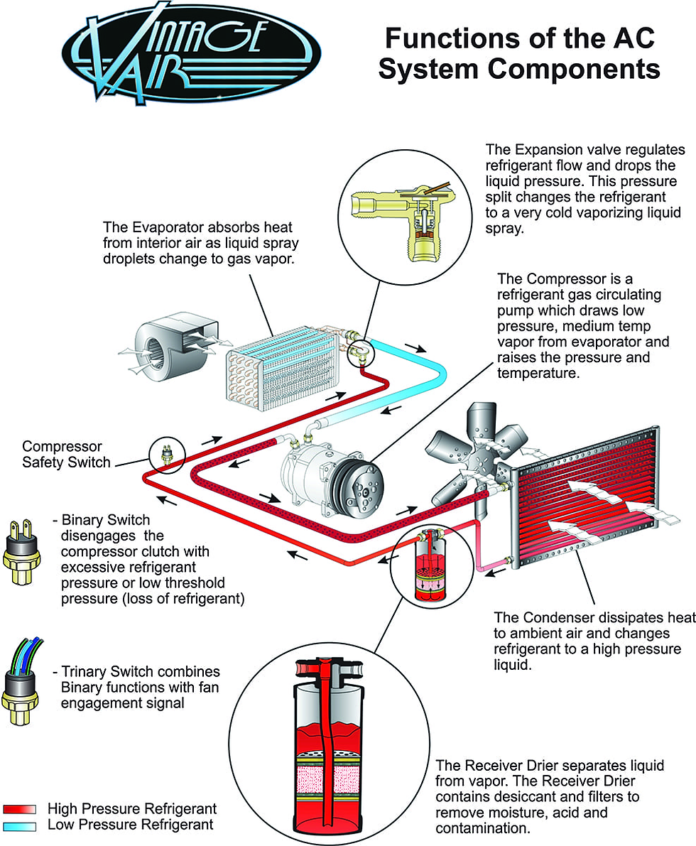
The diagram illustrates the functions of a thermostatic expansion valve automotive air conditioning system, showing how refrigerant cycles through various states to cool a vehicle. The process begins at the compressor, which functions as a circulating pump for the refrigerant gas. The compressor draws in low pressure, medium temperature vapor from the evaporator and mechanically raises both its pressure and temperature. The high pressure refrigerant then exits the compressor and travels through the red lines shown in the schematic.
The heated, high pressure refrigerant flows into the condenser, which is mounted near a fan. The condenser dissipates the heat from the refrigerant into the ambient air, changing the substance into a high pressure liquid. This liquid then continues to the receiver drier. The receiver drier separates the liquid from the vapor and utilizes internal desiccant material and filters to strip out moisture, acid, and any contamination from the system.
After passing through the receiver drier, the high pressure liquid reaches the expansion valve. The expansion valve regulates the flow of the refrigerant and abruptly drops the liquid pressure. This pressure split transforms the refrigerant into a very cold, vaporizing liquid spray. The low pressure spray then enters the evaporator. Inside the evaporator, the refrigerant absorbs heat from the interior air of the car as the liquid droplets convert back into a gas vapor, while a blower fan pushes the resulting cold air into the cabin. The refrigerant, now a low pressure vapor traveling through the light blue lines, returns to the compressor to restart the entire cycle.
The system is monitored by compressor safety switches to prevent damage. A binary switch is designed to disengage the compressor clutch if it detects excessive refrigerant pressure or a critically low threshold pressure, which usually indicates a loss of refrigerant. A trinary switch is also shown as an option, which combines the protective functions of the binary switch with an additional signal to control fan engagement.
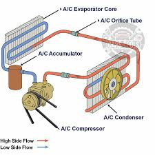
The diagram illustrates an air conditioning system utilizing an orifice tube and an accumulator, a distinct architecture from a thermal expansion valve setup. The cycle begins at the A/C Compressor, which is driven by the engine via a belt. The compressor draws in low pressure refrigerant vapor and compresses it into a high pressure, high temperature gas, pushing it along the red High Side Flow path.
The hot, high pressure gas travels into the A/C Condenser, which sits adjacent to a cooling fan. As air flows through the condenser, the refrigerant dissipates its heat into the atmosphere and condenses into a high pressure liquid.
This liquid refrigerant then flows to the A/C Orifice Tube. Acting as a fixed metering device, the orifice tube restricts the flow of the high pressure liquid and forces a sudden pressure drop. This restriction causes the refrigerant to expand and cool rapidly as it transitions to the blue Low Side Flow path.
The cold, low pressure mixture of liquid and vapor enters the A/C Evaporator Core. Inside the evaporator, the refrigerant absorbs heat from the cabin air passing over the core fins. This heat transfer causes the cold liquid refrigerant to boil and vaporize.
After exiting the evaporator, the refrigerant flows into the A/C Accumulator. The accumulator serves a critical safety function by separating liquid from vapor and trapping any residual liquid refrigerant that did not boil off in the evaporator core. Because the compressor is designed to pump gas and can be destroyed if it attempts to compress a liquid, the accumulator ensures that only low pressure vapor is drawn back into the A/C Compressor to restart the cooling cycle.
Refrigerant Types
R-12
R-12 was the original automotive standard. It was highly efficient, stable, and carried mineral oil exceptionally well throughout the mechanical components to keep compressors lubricated. As a chlorofluorocarbon (CFC), it was phased out globally in the early 1990s due to its severe impact on ozone depletion.
Many original classic car systems and early aftermarket kits were designed specifically for the pressure and flow characteristics of R-12. Retrofitting an older R-12 system to accept modern refrigerants requires flushing the system to remove incompatible mineral oil, adding PAG or Ester oil, replacing the receiver drier, and often adjusting or replacing the expansion valve. Modern refrigerants operate at slightly higher pressures to achieve the same cooling capacity, which can tax older condenser designs.
R-134a and R-1234yf
R-134a became the universal industry replacement for R-12. It is a hydrofluorocarbon (HFC) with excellent thermodynamic efficiency and zero ozone depletion potential. However, it was later identified as having a high Global Warming Potential (GWP), leading to its gradual phase-down in new vehicle manufacturing.
R-1234yf is the current mandated replacement for modern vehicles. It is a hydrofluoroolefin (HFO) with a GWP near zero. From a diagnostic standpoint, the pressure-temperature curve of R-1234yf is nearly identical to R-134a, meaning the system pressures technicians look for on their manifold gauges are largely the same.
The primary difference lies in handling. R-1234yf is classified as mildly flammable (A2L). This classification dictates strict recovery procedures, specialized shop equipment with spark-free vacuum pumps, and heavily regulated storage. The cost per ounce of R-1234yf is also significantly higher, fundamentally changing the economics of a standard system evacuation and recharge.
Typically, the type of refrigerant and the amount of Kg's of oil is listed on a placard under the hood or in the engine bay.
Diagnosing A/C Issues: One of the More Challenging Systems on a Vehicle
A/C systems can be one of the more challenging to diagnose in a vehicle. There are fluid dynamics, mechanicals, and electrical components all in a high-pressure package. Unless technicians are taking time to go through the entire system, they are liable to make a mistake and cost customers more money in the long run. Here is what we think is a fairly in-depth description of the basic diagnostic process. There are certainly more steps, but the site only allows for so large of an image.
The diagnostic trouble tree provides a systematic approach to isolating automotive air conditioning failures. The process begins with a visual and operational inspection. A technician will check belt tension and look for oil stains, which often indicate refrigerant leaks. The primary diagnostic branch then depends on whether the compressor clutch successfully engages when the system is set to maximum cooling. If the clutch does not even engage, usually with an audible click when the A/C turns on, then a compressor is likely the main issue. However, at that point electrical defects should still be considered.
If the compressor does not engage, the technician must determine if the issue is electrical or pressure related by checking the static refrigerant pressure. Adequate static pressure points to an electrical fault in the fuses, relays, pressure switches, or the compressor clutch coil itself. Low static pressure indicates a loss of refrigerant, which triggers a safety switch to protect the compressor from running dry. In this scenario, a positive pressure nitrogen test is required to locate the leak. Vacuum testing alone can mask worn seals by pulling them tightly against their seats. Technicians should also inspect the HVAC drain tube using an electronic sniffer or UV light to rule out a hidden evaporator core leak.
When the compressor engages, manifold gauges are used to analyze the high and low side operating pressures. Specific pressure combinations point to distinct failures. Low pressure on both sides typically means a low refrigerant charge or a restricted expansion device. If the low side drops into a vacuum during operation, moisture is likely trapped inside the system and freezing at the expansion device, creating an ice blockage. High pressure on the low side combined with high pressure on the high side suggests an overcharge, poor condenser airflow, or the presence of non condensable gases.
Conversely, high pressure on the low side and low pressure on the high side usually signifies an internal compressor failure where the unit is no longer pumping. A severe restriction in the high side, such as a plugged orifice tube or blocked condenser, presents as low pressure on the low side and high pressure on the high side. Technicians can pinpoint this type of blockage by feeling the high side lines for a sudden drop from hot to cold. You'll also notice that if the A/C is cold when driving or RPMs are higher, then that can also indicate a blocked orifice tube. Modern parallel flow condensers cannot be effectively flushed and must be replaced if they become internally restricted.
If the gauge readings appear normal but the air is not cold, further investigation is required. If cooling performance improves significantly at higher engine RPMs, the condenser cooling fan or fan clutch may be failing, or the compressor valves might be weak. If the system transitions from heat to cool but fails to reach optimal low temperatures, the exact refrigerant charge must be verified by weight. Additional physical checks involve inspecting the cabin air filter and evaporator core for dirt restrictions, ensuring the temperature blend door seals completely against the heater core, and verifying that the evaporator temperature sensor is preventing the core from freezing over. If all these mechanical components are functioning properly, the fault likely lies within the HVAC control module or interior sensors.
Why a Proper Diagnosis is so Important
A/C Systems have complexities that make repeated diagnostic mistakes or omissisons exceedingly expensive--in ways that others might not.
A/C Systems are labor intensive to work on as they require evacuation and depressurization prior to removing components
A/C Systems require specialized tools to safely replace components, but they are expensive and thereby make the services pricey as well
A/C Systems have componentry in hard to access places (under the instrument panel for example) and too many trips into the car adds to the labor cost over time
There is an element of safety which needs to be considered. While we try not to be hyperbolic about the safety implications of certain vehicle systems, a case can be made that driving in the summer without adequate cooling can be dangerous (especially someplace like Texas or a very humid Summer in the Midwest). Repeatedly having to go back to the shop prolongs a potentially unsafe situation
The Car Conservatory Difference
If you bring your vehicle to our shop, expect some key differences that few other shops (if any) will be transparent about:
Each aspect of the A/C System is tested and verified to be correct. It is reflected in our highly detailed inspection documents
Replacement is suggested based on the evidence presented by the test reuslts--not convenience for the shop. Many shops will replace condensers first because that is the most convenient and 'cheap' fix
If a compressor does fail, we replace the orifice tube automatically as well. Tubes tend to be gummed up over time and clogged when compressors fail
We do not allow temporary A/C Leak fixes (sealants) to be injected into the lines
We do not perform A/C recharges as a bandaid. If a recharge is required, then a leak is suspected and test accordingly. Overcharging the A/C system can cause catastrophic damage to the internals of an otherwise functional compressor



Comments