Your Battery is likely fine; Replacing it may seem like the right move, but there is a better play
- Tyler Betthauser
- Jul 29
- 16 min read

It is particularly demoralizing going to work one morning or getting ready to leave on vacation and the car doesn't want to start. Maybe it simply clicks when turning the key. Sometimes there is simply no action to be seen at all on the dash. Dead batteries are one of the leading failures for OEMs in warranty--probably a very similarly perceived failure rate out of warranty as well. Americans replace a lot of batteries. Some estimates state that 100-120 million lead acid batteries are replaced each year. We think maybe 60% of those batteries are not defective and this high no trouble found rate is due to a lack of maintenance, charging system issues that have nothing to do with the battery, and what amounts to 'incorrect use' of the charging system over time. We discuss how the typical battery system is architected, what functions it performs, why batteries get erroneously replaced so often, how to maintain a battery, and what we suggest to do before spending hundreds of dollars on a new battery.
Most modern vehicles have a 12-volt battery system. It is comprised of: a 12-volt battery (sometimes two), cabling, a starter motor, and an alternator/generator. Electric Vehicles have a similar architecture, but the internal combustion engine is removed and replaced with an even larger battery pack in its place.
12V Battery
The battery acts as the primary energy storage device for the vehicle. Its core function is to supply high amperage direct current to the starter motor during engine cranking, act as a voltage buffer to absorb electrical transients and spikes, and power accessory loads when the engine is off or when total electrical demand exceeds alternator output capacity.
Chemistry and Construction: Absorbing Glass Mat (AGM) or standard flooded lead-acid architectures, featuring alternating positive lead dioxide and negative sponge lead plates immersed in a sulfuric acid electrolyte.
Cold Cranking Amps (CCA): A metric defining the battery's ability to deliver high current at 0 degrees Fahrenheit for 30 seconds while maintaining a terminal voltage of at least 7.2 volts.
Reserve Capacity (RC): The rating denoting how many minutes the battery can continuously deliver 25 amps at 80 degrees Fahrenheit before cell voltage drops below 10.5 volts.
Battery Monitoring Sensor (BMS/IBS): A Hall-effect or shunt-resistor sensor integrated into the negative terminal clamp that continuously reports battery temperature, voltage, and net current flow to the engine control unit or body control module. Some of these are supplemented with software that will actively manage the battery level and can be used to shut down power in the event the battery might die.

12V Battery Internal Architecture
An automotive 12-volt battery is an electrochemical energy storage device composed of independent galvanic cells connected in series. Each individual cell generates an open circuit potential of approximately 2.1 volts, yielding a combined nominal voltage of 12.6 volts at full charge.

Polymer Case and Cell Compartments
The container acts as the structural foundation of the battery, isolating the chemical reactions from the external engine bay environment and organizing the internal components into distinct power assemblies.
Polypropylene Construction: Highly dense, tough polypropylene designed to withstand severe mechanical shock, engine bay thermal cycling, and chemical attack from sulfuric acid.
Cell Partitions: Internal dividing walls that partition the case into six electrically isolated compartments. These partitions prevent electrolyte migration between cells while providing structural rigidity to the outer walls.
Sediment Chambers: Bottom clearance channels in traditional flooded designs that collect and shed active material over the battery's lifecycle, preventing conductive debris from bridging the plates and causing a short circuit.
Plate Grids and Active Material
The plates are the primary engine of the battery, where surface area and lattice structure dictate the maximum rate of current discharge and recharge.
Alloy Grid Framework: Stamped or gravity-cast grids composed of lead-calcium or lead-antimony alloys. The grid acts as both the mechanical skeleton supporting the active material and the primary current collector grid routing electrons to the cell strap. Lead-calcium alloys are typically used to minimize gassing and reduce self-discharge rates.
Positive Active Material: Grids pasted with porous lead dioxide (PbO2), a dark brown crystalline material with a high surface area optimized for rapid ion exchange during cranking events with large amounts of amps.
Negative Active Material: Grids pasted with finely divided sponge lead (Pb), a grey, porous metallic structure designed to maximize interfacial contact with the liquid electrolyte.
Separators and Absorptive Glass Mats (AGM)
Separators sit between alternating positive and negative plates within each cell stack to prevent physical contact and immediate short circuits while allowing the free flow of ions (the particles that have either lost or gained an electrical charge moving across these separators).
Microporous Polyethylene (Flooded): In traditional wet cell batteries, thin, highly porous polyethylene envelopes enclose the positive plates. These envelopes feature ribbed profiles that maintain precise plate spacing while allowing gas bubbles to escape upward.
Borosilicate Glass Fiber Mats (AGM): In Absorbent Glass Mat architectures, fine glass fiber mats replace plastic separators. The mat is compressed between the plates and acts as a capillary sponge, absorbing and holding up to 95% of the liquid electrolyte. This immobilizes the acid, rendering the battery spill-proof and providing mechanical compression that prevents active material shedding under extreme vibration.
Electrolyte Solution
The electrolyte provides the sulfate ions required for the reactions at both plates and serves as the conductive medium for internal ion transport.
Acid-Water Solution: A mixture of approximately 35% sulfuric acid (H2SO4) and 65% deionized water (H2O) by weight, yielding a fully charged specific gravity between 1.265 and 1.280 at 80 degrees Fahrenheit.
Electrochemical Discharge Mechanism: During discharge, sulfuric acid molecules dissociate and react with both the lead dioxide positive plates and the sponge lead negative plates. This sulfate reaction deposits lead sulfate (PbSO4) crystals onto both plate surfaces and extracts sulfate ions from the fluid, converting the electrolyte toward pure water and reducing its specific gravity.
Intercell Connectors and Terminal Posts
The conductive pathways consolidate the current generated across hundreds of individual plates and route it to the external electrical harness with minimal voltage drop.
Through-The-Wall Welding: Lead straps that join the positive plates of one cell to the negative plates of the adjacent cell directly through sealed openings in the partition walls. This shortens the internal current path compared to older over-the-partition designs, reducing internal resistance and increasing cold-cranking voltage.
Terminal Posts: Lead alloy taper posts (SAE standard) or threaded inserts welded directly to the end-cell grid straps. These terminals are engineered with large cross-sectional areas to conduct continuous loads exceeding 1,000 amps without thermal degradation or localized melting.
Power Distribution Center (PDC)
The power distribution center serves as the central hub for routing, protecting, and switching electrical power throughout the vehicle chassis and engine bay. It isolates high current power feeds from low current control circuits and protects wiring harnesses from catastrophic thermal overload during short-circuit events.
Bussed Electrical Centers: Internal architecture utilizing stamped copper lead frames or heavy copper printed circuit boards instead of traditional point-to-point wiring harnesses. These are the fairly large, plastic and metal boxes in the engine bay that have wires coming in and out of it.
Tiered Overcurrent Protection: Integration of high amperage Maxi fuses, J-case cartridge fuses, and standard ATC/ATM blade fuses to protect scaled branch circuits.
Micro-Relays and Solid-State Drivers: Electromechanical switching relays paired with solid-state power modules that control high-current loads like cooling fans, fuel pumps, and headlights without routing heavy current through cabin switches.
Network Gateway Integration: Direct CAN bus or LIN bus connectivity in smart PDCs to report circuit status, relay health, and blown fuse diagnostics directly to scan tools. This particular integration can go wrong quickly when remote telematics access attempts to turn on the vehicle for data collection routines and OTA Updates. Sometimes, the vehicle can get stuck on and not be able to shut down.

Chassis and Engine Block Grounding
The grounding system completes the electrical return path back to the battery negative terminal for every active electrical circuit on the vehicle. Because steel chassis rails and aluminum engine blocks act as the primary return conductors, dedicated bonding straps ensure low-resistance return paths for high-current electrical loads like the starter armature and alternator rectifier assembly.
Bonding Cables: Thick braided copper straps or 2/0 to 4-gauge welding-style cables bridging the engine block, transmission bellhousing, chassis frame rails, and battery negative post.
Anti-Corrosion Eyelet Terminals: Zinc-plated or tinned copper ring terminals secured with star washers that bite through painted or anodized surfaces to establish bare-metal contact.
Dedicated Grounds: Isolated, low-noise grounding points used specifically for sensitive sensors, audio infotainment systems, and airbag modules to prevent AC alternator ripple from causing sensor interference.
Ignition Switch and Push-to-Start System
This system acts as the gateway for transitioning the vehicle power state through Off, Accessory, Run, and Crank modes. In modern keyless architectures, it functions as a low-voltage digital signal interface that sends electronic authorization requests to the body control module rather than directly switching high-current power feeds across mechanical tumbler contacts.
Tactile Power Switches: Momentary low-voltage pushbuttons or multi-position mechanical key cylinders with spring-return cranking positions.
Immobilizer Authentication: Integrated radio frequency identification (RFID) or antennas that read encrypted transponder chips inside the ignition key or smart fob before enabling power distribution.
Redundant Output Channels: Dual-channel signal pathways that verify switch position to prevent unintended starter engagement or accidental engine shutdown while driving.

Starter Relay and Safety Interlocks
The starter relay allows a signal from the ignition switch or body control module to switch the intermediate current required to energize the heavy starter solenoid coil. Safety interlocks interrupt this control circuit to prevent engine cranking unless specific vehicle safety criteria are met.
Electromechanical ISO Relays: Standard 4-pin or 5-pin heavy-duty relays housed within the under-hood power distribution center capable of handling 30 to 50 amps of inductive solenoid draw.
Transmission Range Sensors: Digital neutral safety switches integrated into the automatic transmission valve body or manual shift linkage that hold the starter control circuit open in any gear position other than Park or Neutral.
Clutch Interlock Switches: Dual-stage potentiometer or Hall-effect switches mounted to the manual transmission clutch pedal assembly to verify 100% pedal depression before closing the starter circuit.
Starter Solenoid and Motor
The starter assembly converts electrical energy into mechanical torque to rotate the engine at sufficient speed (typically 150 to 300 RPM) to initiate enough fuel and spark to run in a self-sustained way. The integrated solenoid acts simultaneously as a electrical contactor and a linear mechanical actuator.
Planetary Gear Reduction: Internal planetary gearsets that multiply motor torque output by ratios up to 4:1, allowing modern starters to use smaller, lighter permanent magnet motors while turning over high-compression engines.
Overrunning Drive Clutch: A specialized mechanical one-way clutch (Bendix drive) that allows the pinion gear to drive the flywheel ring gear during cranking but disengages instantly when engine RPM exceeds starter armature speed, preventing mechanical overspin destruction.
High-Current Solenoid Contacts: Stationary copper bolts and a movable copper contact disc inside the solenoid cap capable of bridging 150 to 300+ amps of current without welding shut under arcing loads.
Series-Wound or Permanent Magnet Armatures: Motor designs optimized for high initial stall torque to overcome engine static friction and cylinder compression resistance.

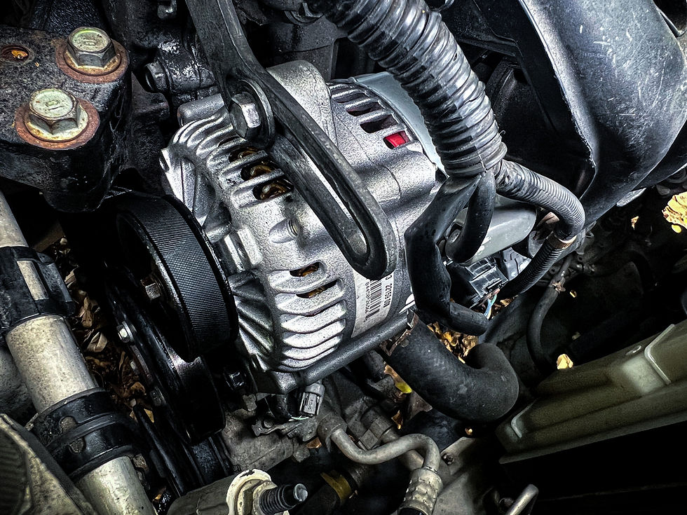
Alternator
The alternator converts mechanical energy from the spinning engine crankshaft into direct current electrical energy to power all operating vehicle systems and recharge the battery. It dynamically scales its power output based on current electrical demand and battery state-of-charge parameters calculated by the engine management system.
Three-Phase Stator and Rotor: Stationary copper windings arranged in three distinct phases surrounding a spinning electromagnetic rotor coil powered through carbon brushes and copper slip rings.
Bridge Rectifier: An internal or external heat-sinked array of silicon diodes or MOSFETs that convert the alternating current generated in the stator into clean direct current for the vehicle electrical bus.
Smart Voltage Regulation: An internal electronic regulator or engine control unit interface that modulates pulse-width modulated (PWM) ground signals to the rotor field winding, maintaining target system voltage between 13.8V and 14.8V. Some vehicles, like the Malibu we worked on recently, had 6 different charging modes!
LIN Bus Communication: Bi-directional data networking allowing the engine control module to execute smart charging strategies, such as dropping alternator field current during wide-open throttle acceleration to eliminate parasitic engine load, or spiking charging voltage during vehicle deceleration for regenerative battery recovery.
Overrunning Alternator Decoupling Pulley (OAD/OAP): A specialized drive pulley containing an internal spring and one-way clutch that absorbs crankshaft torsional vibrations and belt whip during gear shifts, significantly extending serpentine belt and tensioner bearing lifecycles.
Batteries are Replaced Far Too Often
When batteries are replaced under warranty, the true failure rate is smaller than you'd think. North of 60% of batteries can be reconditioned and function properly. The battery and its cells were fine, but yet replaced. Many times, manufactures can recycle these and re-sell them on the market. However, dead (or heavily depleted) batteries are usually just a symptom. Why are batteries so often replaced then--even if they are likely still good?
Sometimes Speed Beats Accuracy
Many drivers replacing batteries are crunched for time. Some are on vacation, on their way to work, stuck in the parking lot at work, or stuck at home. Customers just want their car fixed and with haste. Unfortunately, we often see vehicles come into the shop after the client has already replaced the battery and the root cause was not addressed; ultimately, they are delayed even longer and risk the depletion of another battery. Some of our clients have spent over $750 on batteries alone before coming into our shop.
Most Shops & Clients Won't Spend the Time to Test the Battery Thoroughly
Typically, a battery is condemned early because it is the most convenient and fast action. And, because replacing a battery can actually mask an issue, the customer thinks they have gotten a quick win. Unfortunately, that is not going to work in the medium or longer term. Shops should be spending more time eliminating the battery as the culprit rather than simply replacing it. There's a few tests which can assess battery failure: Digital Multimeter, Conductance, Load Testing, and PicoScope 4425A Digital Storage Oscilloscope.
Digital Multimeter
One of the easiest, but not most robust, methods of testing is using a multi-meter.

A multimeter allows the user to measure many different aspects of the electrical system such as volts and resistance in a circuit. When testing with a multimeter technicians should expect around 12 volts to be shown on the tool. If you start the vehicle and that voltage reading falls below 9.6 volts it is a reasonable clue that the battery has degraded internals. Testing a battery with a multimeter does a reasonable job as a static test, but should only be the first test in a sequence of tests.
Conductance Tests
Conductance testers utilize battery source voltage to measure current and infer resistive metrics used to estimate internal battery states. This technology is similar to the use of multimeter when performing basic testing procedures (voltage, resistance, and current measurements) to estimate whether a replacement is recommended or not. a fast, non-invasive diagnostic method used to evaluate a battery's health. It works by sending a small alternating current (AC) signal through the battery and measuring the response to determine its internal resistance and capacity to deliver power. Conductance (measured in Siemens or Mhos) reflects the condition of the battery's internal plates. As a battery ages, sulfation and plate degradation reduce its conductive surface area. The tester checks for these issues in a matter of seconds without placing a heavy, draining load on the battery.

Load Testing
It is possible that static testing might pass, but fail under a load. A significant portion of our clients have intermittent problems that other shops can't seem to solve. Load testing checks if your battery can hold enough power while under a heavy load. A healthy 12V battery should maintain a voltage above 9.6 volts throughout the 15-second load test (adjusted slightly higher or lower depending on freezing or hot temperatures).
The science behind load testing relies on Ohm's Law (V = I × R) and the concept of internal resistance. A healthy battery holds a static charge around 12.6 V. When a high current load (I) is applied, the battery's internal resistance (R) causes the terminal voltage (V) to drop. As a battery ages, sulfation builds up on its internal plates. This increases internal resistance. When a high load is applied to a failing battery, its increased internal resistance causes the voltage to plunge below the acceptable threshold (typically 9.6 V at room temperature), signaling that the battery can no longer reliably start an engine.

PicoScope 4425A Digital Storage Oscilloscope
The PicoDiagnostics Battery Test is a software diagnostic tool feature bundled with PicoScope Automotive that evaluates the complete 12V or 24V starting and charging system. It uses a live engine crank as a real-world load test to measure voltage drop, starter current, internal battery resistance, and alternator output. Unlike traditional handheld carbon-pile or small conductance testers that inject a minor AC signal or brief synthetic load, the Pico test uses the vehicle’s own starter motor to place a massive, authentic electrical load on the battery. By simultaneously capturing voltage and current during cranking, it measures how much the voltage sags under peak current. The ratio of voltage drop to current draw allows the software to compute the exact internal resistance of the battery and wiring circuits. It extends beyond the battery itself by tracking the alternator's charging voltage and diode ripple once the engine starts, uncovering hidden resistance in positive and negative starter cables that standard testers miss.
These tests can tell a technician that a battery is bad, but the results need to be analyzed in context of the other symptoms being experienced by the customer. There are bad batteries that also fail alongside a bad starting and charging system. Regardless, these fairly simple tests should be conducted when a battery is suspected to have failed.
Batteries Do Still Fail, Even if the Rate is Small
Batteries are not failure proof. Cells within the batteries do fail and sometimes fail with a failing charging system. Yes, there can be multiple root causes for a failing battery; The battery itself and the charging system. A kind of feedback loop can exist where replacing a battery, but not the parts of the failing charging system, will result in more dead batteries.
We use a fishbone diagram to document the typical types of failure modes for a battery:
Positive Grid Corrosion
This is a chemical process where the lead alloy forming the positive grid slowly converts to lead oxide. High temperatures, overcharging, and heavy cycling accelerate this conversion. As the corrosion progresses, it causes the plates to physically expand, increases internal resistance, and eventually degrades the power capability of the battery until it fails.
Sulphation
Normal battery discharge creates soft lead sulphate, which is safely reversed during charging. If a battery is left in a discharged state, undercharged, or poorly maintained, this soft material hardens into crystalline sulphate. This permanent crystallization physically damages the plates, reduces total capacity, and increases internal resistance.
Internal Shorts
These develop silently inside the battery and fall into two categories. Hard shorts come from manufacturing defects, like lumps of active paste breaching the separators. Soft shorts happen from extreme deep discharges that dissolve lead into the electrolyte, which then gets trapped in the separators. Both cause sudden capacity loss, excessive heat generation, and severe fire risks.
Electrolyte Dry-Out
Valve regulated lead-acid batteries are sealed, meaning lost fluid cannot be replenished. Excessive heat, improper charging voltage, or poor ventilation causes them to lose electrolyte moisture permanently. This unrecoverable loss increases internal impedance, raises the operating temperature, and destroys the necessary contact between the plates and the electrolyte.
Thermal Runaway
This is a dangerous, self-reinforcing loop where heat and electrical current feed into each other. As the battery heats up, its internal resistance drops, allowing more current to pass. This increased current generates even more heat, pulling in more current, which spirals rapidly and causes catastrophic failure within hours. Thermal Runaway Propagation (TRP) is most often associated with the large electric vehicle batteries.
Pressure Build-Up and Venting
When gas generation inside the sealed battery outpaces its internal recombination rate, internal pressure spikes. The battery is forced to open its safety valves and vent the gas to avoid exploding. This directly causes electrolyte loss, accelerating the dry-out process and permanently altering the cell chemistry. Usually this manifests as a bloated and or smoking battery.
SEI Layer Build-Up
The solid electrolyte interface layer naturally thickens over the life of the battery. As it grows, it progressively increases internal impedance. This causes a higher voltage drop under load, generates more heat during normal operation, and permanently limits the maximum current the battery can deliver safely.
Lithium Plating
Instead of lithium ions smoothly inserting themselves into the graphite anode during charging, they accumulate on the surface as metallic lithium deposits. This grows into sharp dendrites that can pierce internal separators, leading to immediate internal short circuits, potential cell rupture, and severe thermal runaway.
Non-Uniform Ageing
Different physical sections of a single cell degrade at different rates rather than wearing out evenly. This creates localized weak spots inside the battery structure, resulting in uneven current distribution, reduced overall capacity, and unpredictable voltage responses under heavy loads.
Hardware, Software, and Calibration Faults
The battery management system serves as the intelligence of the pack. When its physical circuits fail, its software malfunctions, or its sensors lose calibration, the system fails to execute emergency disconnections, misreads cell states, and fails to issue critical warnings before a catastrophic event occurs.
Loss of Limit Protection
Without a functioning battery management system to enforce boundaries, the battery loses crucial temperature controls and current limits. The system can be overcharged or over-discharged without intervention, pushing the cells past their physical breaking points and risking immediate fires or explosions.
Unmitigated Cell Imbalance
A compromised battery management system stops equalizing the voltages across individual cells in the pack. Some cells are forced to operate at much higher or lower voltages than their neighbors to carry the load, placing excessive stress on the weaker cells and drastically accelerating their physical degradation.
Connection Degradation
The physical metal links between individual batteries break down over time. This degradation is driven by environmental corrosion, ambient vibration from the facility, and the constant expansion and contraction of hardware during repeated thermal cycling.
High Resistance and Excessive Heating
As those degraded inter-cell connections lose solid contact, their electrical resistance increases. During heavy load demands, this resistance acts as a bottleneck that generates extreme localized heat. In severe cases, this heat can melt terminal posts and ignite surrounding materials.
String Voltage Imbalances
Poor connections disrupt the voltage across the entire connected string of batteries. This masks the true capacity of the array, creates unequal charging and discharging behavior across the system, and forces the battery plant to operate inefficiently even if the individual battery cells are perfectly healthy.
Maintaining a Battery for Reliability
Maximizing the lifecycle of a 12-volt battery requires active management rather than waiting for a failure. Lead-acid batteries degrade rapidly when left in a discharged state, and proactive maintenance is the most effective way to prevent irreversible internal sulfation.
Optimize Drive Cycles
One of the best methods to maintain battery health is to allow the charging system adequate time to work. Starting the engine requires a massive discharge of high-amperage current. If a vehicle is consistently driven on short trips lasting less than 15 minutes, the alternator lacks the time to replenish the capacity lost during the cranking event. Vehicles need longer, continuous drives at cruising speeds to allow the engine control module to properly manage the charge rate and bring the battery back to full capacity.
Use a Smart Battery Maintainer
Vehicles that sit idle for more than a week or two should be connected to a smart battery maintainer. Traditional trickle chargers push a constant current that can overcharge the system and dry out the electrolyte, especially in modern AGM batteries. A multi-stage smart charger monitors the battery's internal resistance and state of charge, floating the voltage only when necessary to prevent sulfation without damaging the internal cells.
Limit Key-Off Electrical Draw
Running the infotainment system, interior electronics, or exterior lighting on battery power alone will quickly degrade the system. Deep cycling a standard automotive starting battery below 50 percent capacity permanently damages the lead plates. Furthermore, modern vehicles utilize heavily networked architectures where control modules wake up simply by detecting a key fob nearby. Store key fobs away from parked vehicles to allow the network to enter a full sleep state, which significantly reduces parasitic electrical drain.
Physical Inspection and Vibration Control
Vibration is highly destructive to internal battery components. Constant shaking causes the active material to shed from the plate grids. This material accumulates in the bottom sediment chambers and eventually bridges the plates, causing an internal short circuit. Always ensure the factory battery tie-down bracket is properly secured. You should also periodically inspect the positive and negative terminals for acidic corrosion. Keeping the terminals clean and ensuring the clamps are tightly seated prevents high-resistance voltage drops that force the alternator to work harder than necessary.


Comments